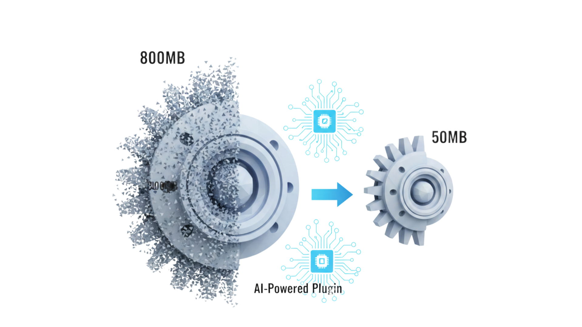
Imagine this scenario: You've just finished a high-resolution 3D scan or a detailed ZBrush sculpt. The model looks incredible, but the file size is a staggering 800MB. You try to drag it into your slicer (Cura, PrusaSlicer, or Bambu Studio), and your computer freezes. Ten minutes later, the software crashes.
This is the "Polygon Bloat" crisis facing modern 3D printing. As scanning hardware and sculpting software improve, STL files are becoming unmanageably large, often containing millions of triangles that are smaller than the resolution your 3D printer can physically reproduce.
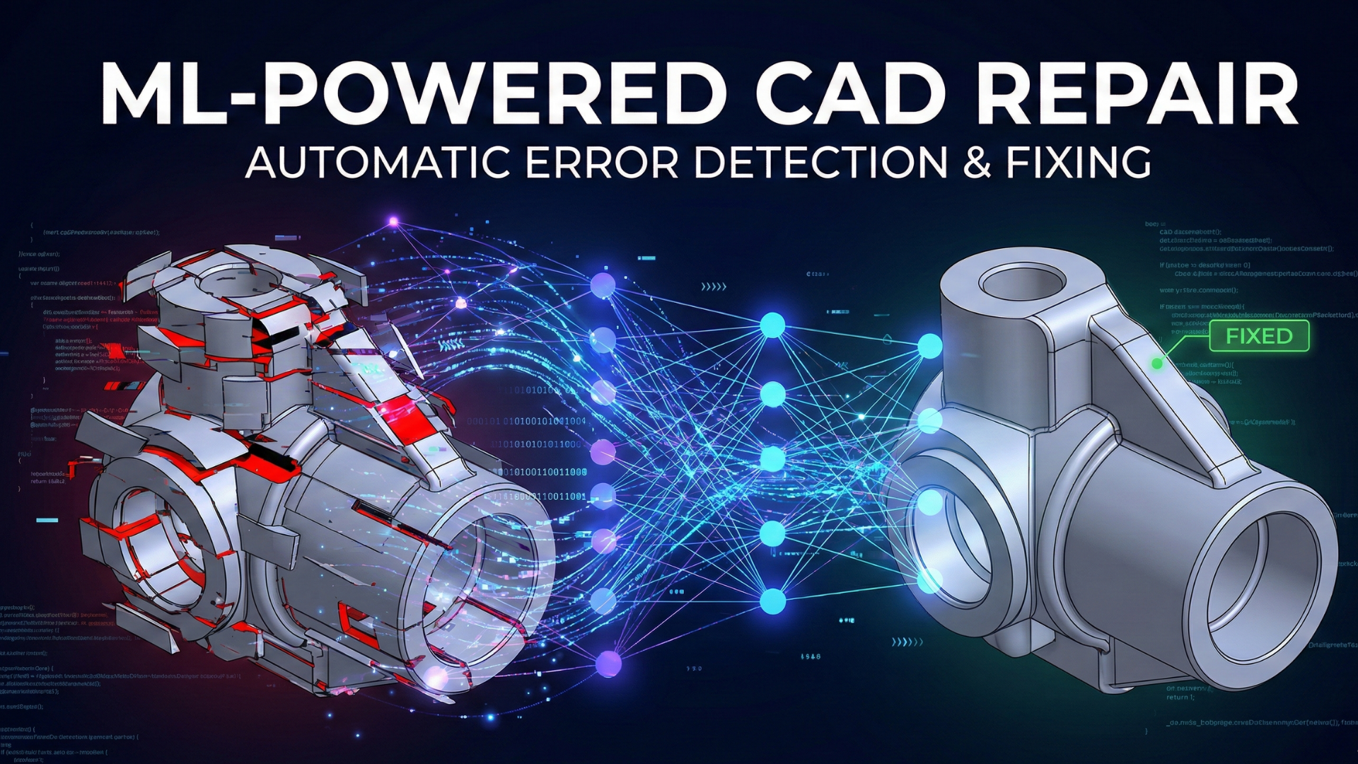
The old solution was "blind decimation"—randomly deleting triangles and hoping for the best. But in 2024, AI-powered algorithms and smart topology tools have revolutionized this process. These tools can now "read" your model, understanding which details are essential and which are redundant, allowing you to reduce file sizes by up to 90% with zero visible loss in print quality.
In this guide, we will explore the best AI-driven plugins and workflows to streamline your 3D printing process, save drive space, and stop your slicer from lagging.
Table of Contents
- The "Bloat" Problem: Why Slicers Struggle
- AI vs. Traditional Decimation: The Tech Explained
- Top 4 AI-Enhanced Tools for STL Compression
- Step-by-Step: The Smart Reduction Workflow
- Pro Tip: Solving the Large File Collaboration Gap
- Quality Assurance: The Deviation Map Technique
- Common Mistakes That Ruin Prints
- Conclusion
- References
The "Bloat" Problem: Why Slicers Struggle
To understand the solution, we must first understand the bottleneck. An STL file is simply a list of triangles (mesh) that form a 3D surface.
The Resolution Mismatch
Most consumer FDM (Fused Deposition Modeling) printers have a nozzle diameter of 0.4mm. Even high-end SLA (Resin) printers rarely resolve details smaller than 0.05mm. However, raw 3D scans often contain triangles that are 0.001mm in size.
This creates a massive inefficiency: your computer works overtime to process millions of triangles that will eventually be melted into a single blob of plastic. The goal of optimization is not just to make the file smaller, but to match the mesh resolution to the printer resolution.
AI vs. Traditional Decimation: The Tech Explained
Why can't you just use the standard "Reduce" slider in your software?
Traditional Algorithms (The "Dumb" Approach)
Standard decimation uses a mathematical approach called Quadric Edge Collapse. It calculates the cost of collapsing an edge based on geometric error. While effective, it is "blind" to the object's features. It treats a flat base and a detailed dragon scale with similar mathematical priority. If you reduce too much, sharp edges become jagged, and smooth curves turn into blocky polygons.
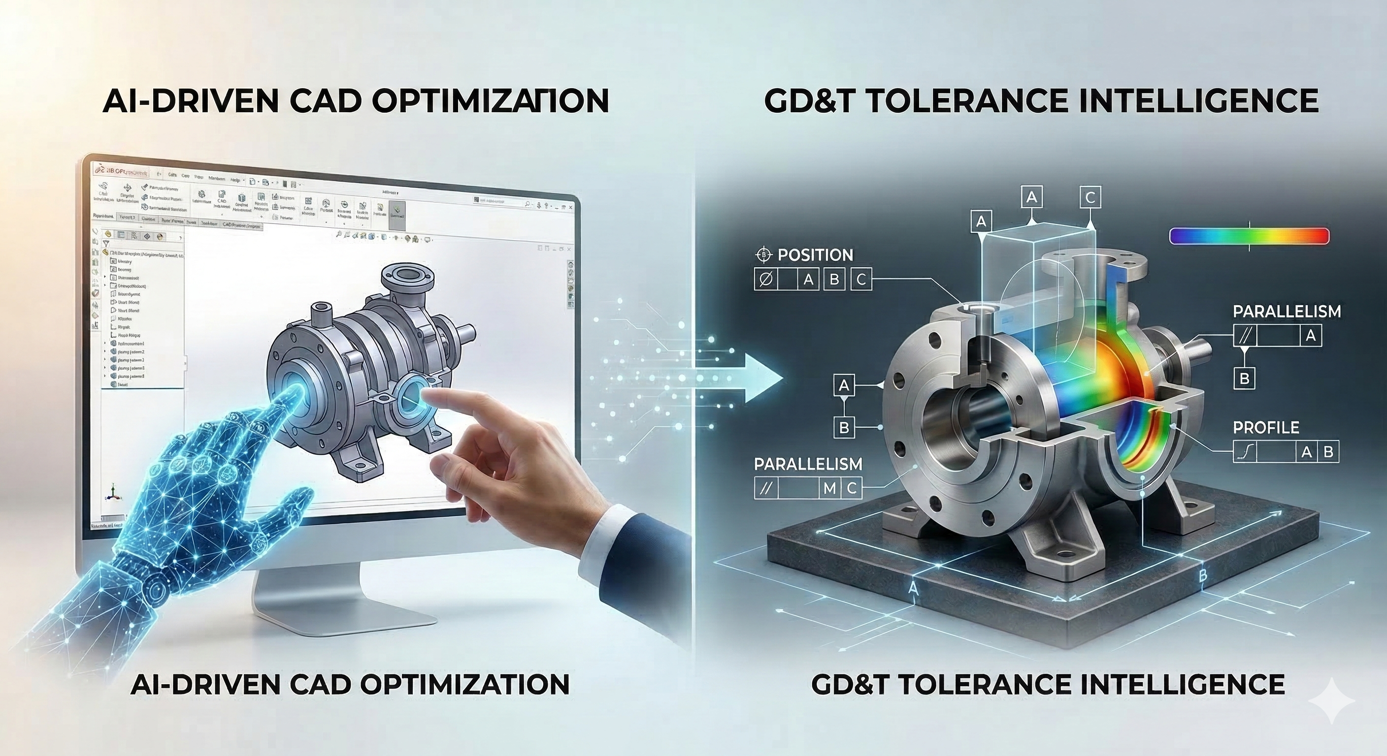
AI and Smart Topology (The "Intelligent" Approach)
AI-driven or "Smart" algorithms use feature detection to analyze the geometry before reducing it.
- Curvature Preservation: The algorithm detects high-curvature areas (eyes, text, sharp edges) and "locks" the triangle density in those zones.
- Planar Simplification: It aggressively removes triangles from flat surfaces (bases, walls) where high resolution is wasted.
- Retopology: Instead of just deleting triangles, some AI tools rebuild the mesh entirely with square polygons (quads) that follow the flow of the model, resulting in a cleaner surface with fewer data points.
"The difference is like using a scalpel instead of a sledgehammer. AI tools remove the fat while preserving the muscle of the model."
Top 4 AI-Enhanced Tools for STL Compression
While direct "AI Plugins" for slicers are still emerging, these standalone tools and plugins are the industry leaders for smart reduction.
1. QuadRemesher (The Gold Standard)
While technically an auto-retopology tool, QuadRemesher (available as a plugin for Blender, Fusion 360, and Max) is widely considered the best "smart" reducer on the market.
- How it works: It uses advanced algorithms to completely regenerate the surface of your model using organized quads rather than messy triangles.
- Best for: Organic shapes, sculptures, and 3D scans where surface flow matters.
2. MeshInspector (Smart Analysis)
MeshInspector is a powerful tool for professionals. It doesn't just reduce; it analyzes.
- The AI Edge: It offers automated inspection tools that highlight mesh deviations and wall thickness issues. Its simplification algorithms allow you to set a specific "dimensional tolerance" (e.g., 0.05mm), ensuring the software never alters the shape more than your printer can handle.
3. Nano3D Tech (Web-Based AI)
For users who prefer not to install heavy software, Nano3D offers an AI-assisted web platform specifically for 3D printing.
- Feature: It focuses on "Smart Simplification," aiming to preserve the outer shell's integrity specifically for slicing engines. It's a quick, drag-and-drop solution for reducing file size without tweaking settings.
4. Blender + "Decimate" (The Free Powerhouse)
While Blender is free, its Decimate Modifier has a "Planar" mode that acts intelligently.
- Planar Mode: This mode looks for flat surfaces and merges triangles specifically in those areas, leaving detailed curves untouched. It is manual but incredibly effective for mechanical parts.
Step-by-Step: The Smart Reduction Workflow
Here is a battle-tested workflow to reduce a 500MB raw scan down to a crisp 50MB print-ready file using Blender (free) or similar tools.
Step 1: Clean the Noise
Before reducing, you must remove "floating artifacts." 3D scans often have tiny floating particles that confuse reduction algorithms.
- Action: Use "Select Linked" -> "Invert" -> "Delete" to remove loose geometry.
Step 2: Apply Adaptive Reduction
Do not use a fixed percentage (e.g., "Reduce by 50%"). Instead, use a Deviation-Based approach if your software supports it, or a Ratio approach with visual checking.
- Import your high-res STL.
- Apply Decimate Modifier (Collapse mode).
- Target: Aim for a ratio of 0.1 (10%) initially.
- Check the Wireframe: Toggle "Wireframe" view. Look at the curved areas. If the wireframe looks dense on flat spots, switch to Planar mode first to clean those up.
Step 3: The "Slicer Preview" Test
Never trust the viewport. Export the reduced STL and open it in your slicer.
- Layer View: Slice the file and zoom in on a curved section. If you see "faceting" (straight lines instead of a curve) in the G-code preview, you have over-reduced.
Pro Tip: Solving the Large File Collaboration Gap
Even after optimizing a file from 500MB to 50MB, you still face a major hurdle: Collaboration.
If you are working with a client or a remote team, emailing a 50MB STL file is often impossible (most email limits are 25MB). Using WeTransfer is slow, and worst of all, your client likely doesn't have the software to view the file properly.
This is where VizCAD becomes an essential part of the workflow.
Instead of struggling with file transfers and compatibility issues:
- Upload your optimized (or original) STEP/STL file to Vizcad's secure cloud workspace.
- Generate a Smart Link: Send a single URL to your client or engineer.
- Instant Browser Review: They can rotate, zoom, and inspect the 3D model instantly in their web browser—no installation, no high-end GPU required.
Why this matters: Vizcad allows you to bypass the hardware limitations of your stakeholders. You can keep your master files safe in the cloud while giving teammates the ability to comment and approve designs in real-time. It bridges the gap between "File Optimized" and "Project Approved."
Quality Assurance: The Deviation Map Technique
For professional engineering prints, "it looks okay" isn't good enough. You need data. You can use a technique called Geometric Deviation Mapping to prove your reduced file is accurate.
How to do it (using CloudCompare or GOM Inspect):
- Import Original: Load the 500MB master file.
- Import Reduced: Load your 50MB optimized file.
- Align: Use the software's "Best Fit Alignment" to overlap them perfectly.
- Compute Distance: Run a "Hausdorff Distance" or "Mesh-to-Mesh Deviation" check.
The Result: You will get a heat map.
- Green: 0mm deviation (Perfect).
- Red/Blue: Deviation exists.
The Rule of Thumb: As long as the deviation is less than your printer's layer height (e.g., <0.1mm or <0.2mm), the print will be physically identical to the original [1].
Common Mistakes That Ruin Prints
1. Reducing Mechanical Fits
Be extremely careful when reducing parts that need to screw together or fit into a slot. Reduction algorithms often "shrink" corners or smooth out threads.
- Fix: Use a "Vertex Group" to mask off the threads or mechanical interfaces, preventing the reduction tool from touching those specific areas.
2. Ignoring "Non-Manifold" Geometry
Aggressive reduction can sometimes create holes in the mesh (non-manifold edges). A slicer cannot print a model with holes.
- Fix: Always run a "Make Manifold" or "Repair" pass (available in Windows 3D Builder or Meshmixer) after you reduce the file size.
3. Optimizing for the Wrong Technology
A file optimized for FDM (0.4mm nozzle) will look blocky on a Resin (SLA) printer.
- Guideline: For FDM, a 10MB file is usually sufficient for a complex model. For Resin, you may need to keep the file at 50-100MB to preserve the microscopic details [2].
Conclusion
The days of struggling with gigabyte-sized STL files are over. By leveraging AI-driven topology tools and smart adaptive reduction, you can maintain professional print quality while slashing file sizes by 90% or more.
Key Takeaways:
- Stop guessing: Use adaptive reduction based on geometric deviation (e.g., 0.05mm), not arbitrary percentages.
- Protect features: Use tools like QuadRemesher or Planar Decimation to keep sharp edges sharp.
- Streamline sharing: Use browser-based tools like Vizcad to share and review these models without the headache of file transfers.
- Verify: Always check the layer preview in your slicer before hitting print.
Optimizing your mesh isn't just about saving hard drive space—it's about faster slicing, smoother workflows, and better prints.
References
[2] Prusa Knowledge Base – Simplify Mesh (Polygon Count vs. Print Quality)
[3] Formlabs – Meshmixer Tutorial: Tips to Edit STL Files for 3D Printing
About the Author

Ferhat RudvanoğullarıMechatronics Engineer
Ferhat RUDVANOĞULLARI is a Mechatronics Engineer and the founder of Viz-CAD. Throughout his career, he has transferred the engineering perspective and system development experience gained from R&D projects into Viz-CAD, aiming to redefine engineering design processes through web-based solutions. Recently, he has focused his work on web-based 3D technologies and artificial intelligence applications, developing accessible, scalable, and innovative design infrastructures by bringing engineering tools to the browser environment.